I've recently worked on a project that I had the parts for for quite some time, but never got started on. I salvaged this XY stepper head from a cheap chinese 'laser show' which had no programmable inputs and a nonfunctional 'auto sound' mode that would only repeat the same three patterns over and over again. The laser that was built into it had its pump diode die a thermal death a long time ago so I shelved it and planned on modifying it eventually.
I decided to look into stepper motors and their control schemes and found that it would be rather simple to code the subroutines for single coil per step movements on an arduino. Once I realized this, it was time to start work.
Now, steppers aren't particularly fast or accurate, especially at the upper limits of their speed, as they start to miss steps. I can get these cheap ones to about 2.75mS/step and no further without losing steps, but that's good enough for me.

Instead of driving the motors with an intermediary IC (or even an entire dedicated board) designed for stepper control I decided to just go discrete electronics with NPN bipolar transistors and small signal fast diodes for flyback recovery. I'm only driving one coil at a time since I don't have the pinout for the motor coils and it is a 5pin unipolar motor with common ground. It doesn't appear that it is two center tapped coils with common CT., but rather it looks to be four individual coils with tied ends. I know there are ICs that can use the two center tapped coils in a bipolar drive method to allow microstepping and such but I don't think that is possible with these steppers. The reason for the NPN BJTs is that the arduino can only sink or source 40mA maximum per I/O line and these steppers draw about 90mA @ 9V (and they're 12V steppers, but run down to 5V min).
I experimented with increasing the motor voltage in hopes of gaining speed, but no increase in accuracy or speed was measured between 5.7V and 12V. I found that I got the best results with a 2.75mS ontime and 250uS offtime.
Unfortunately the mechanical issues of rotor inertia, jitter, and flicker could not be eliminated. Only the simplest of designs could be reproduced without a large degree of error. Attempting to reproduce a number 8 results in two vertically stacked squares with a space in between them, tethered in the center. (see video #3).
For the amount of work it takes to get this poor result it isn't worth continuing further. It was a good exercise and a fun experiment if you ignore the 12hours or so of coding. I wrote nearly 2500 lines of code for this, and while most were just edited copy/paste, it was still a nightmare of a job. There are 64 subroutines written for motor advancement: 1 to 16 steps forward, 1 to 16 steps backward, each for two axes.
The code is straight forward; manually pulse each coil for a set time in grouped ordered bunches to produce movement. The Achilles heel is that this is completely open loop. There is no way to detect or remember what the last coil used was so when you go back to the same axis you have to manually insert code to bridge the gaps to ensure it doesn't inadvertently reverse steps or miss steps entirely.
For example:
void loop(){
xplus4();
xminus4();
}
Thus pulses coils as such: 1 2 3 4 4 3 2 1. Notice the double pulse of coil 4? This means the rotor will sometimes make 4 positive movements and then three negative ones, and other times it will make three positive and three negative, depending on where the rotor was when the first pulse to coil 1 hit.
If we wanted to fix this we would have to do as so:
void loop(){
xplus4();
digitalWrite(1, HIGH);
delayMicroseconds(tON);
digitalWrite(1, LOW);
 delayMicroseconds(tOFF);
xminus4();
}
 This pulses as such: 1 2 3 4 1 4 3 2 1. Now we'll always get four positive and four negative steps, but occasionally we'll get five positive initially, again depending on rotor position.
Consequently, the subroutine for xplus5 looks just like 1 2 3 4 1, so I would have just used it instead, but I wanted to illustrate the process more precisely. This example has a pre-written subroutine that fits in as a correction, but most transitions do not.
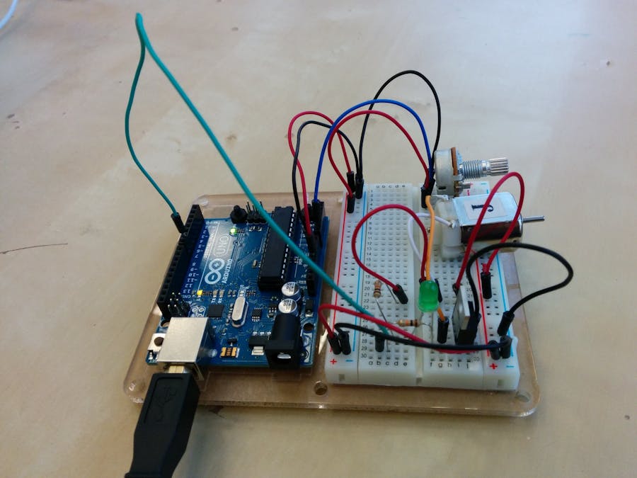
The hardware circuitry is simple, as this schematic and picture show:

Comments are closed.
My approach basically involves trashing a $100 scanner. Out all the electronics, the CCD image sensor, and the stepper motor mechanism, and built a new mechanism to hold it all together, and rotate the CCD and lens assembly to scan its environment, instead of a piece of paper. First we need to add components to control the stepper motors: Type 'step' in the Filter box of the Component Toolbox then select the '4 Wire Stepper Motor' component (Picture 1), and drop two of them it in the design area Click in the 'Out' box containing the pins of the Stepper1 component to start connecting all the Out pins at once (Picture 2) Move the mouse over the 'Digital' input pin of.
I decided to look into stepper motors and their control schemes and found that it would be rather simple to code the subroutines for single coil per step movements on an arduino. Once I realized this, it was time to start work.
Now, steppers aren't particularly fast or accurate, especially at the upper limits of their speed, as they start to miss steps. I can get these cheap ones to about 2.75mS/step and no further without losing steps, but that's good enough for me.

Instead of driving the motors with an intermediary IC (or even an entire dedicated board) designed for stepper control I decided to just go discrete electronics with NPN bipolar transistors and small signal fast diodes for flyback recovery. I'm only driving one coil at a time since I don't have the pinout for the motor coils and it is a 5pin unipolar motor with common ground. It doesn't appear that it is two center tapped coils with common CT., but rather it looks to be four individual coils with tied ends. I know there are ICs that can use the two center tapped coils in a bipolar drive method to allow microstepping and such but I don't think that is possible with these steppers. The reason for the NPN BJTs is that the arduino can only sink or source 40mA maximum per I/O line and these steppers draw about 90mA @ 9V (and they're 12V steppers, but run down to 5V min).
I experimented with increasing the motor voltage in hopes of gaining speed, but no increase in accuracy or speed was measured between 5.7V and 12V. I found that I got the best results with a 2.75mS ontime and 250uS offtime.
Unfortunately the mechanical issues of rotor inertia, jitter, and flicker could not be eliminated. Only the simplest of designs could be reproduced without a large degree of error. Attempting to reproduce a number 8 results in two vertically stacked squares with a space in between them, tethered in the center. (see video #3).

Stepper Motor Controllers
For the amount of work it takes to get this poor result it isn't worth continuing further. It was a good exercise and a fun experiment if you ignore the 12hours or so of coding. I wrote nearly 2500 lines of code for this, and while most were just edited copy/paste, it was still a nightmare of a job. There are 64 subroutines written for motor advancement: 1 to 16 steps forward, 1 to 16 steps backward, each for two axes.
The code is straight forward; manually pulse each coil for a set time in grouped ordered bunches to produce movement. The Achilles heel is that this is completely open loop. There is no way to detect or remember what the last coil used was so when you go back to the same axis you have to manually insert code to bridge the gaps to ensure it doesn't inadvertently reverse steps or miss steps entirely.
For example:
void loop(){
xplus4();
xminus4();
}
Thus pulses coils as such: 1 2 3 4 4 3 2 1. Notice the double pulse of coil 4? This means the rotor will sometimes make 4 positive movements and then three negative ones, and other times it will make three positive and three negative, depending on where the rotor was when the first pulse to coil 1 hit.
If we wanted to fix this we would have to do as so:
void loop(){
xplus4();
digitalWrite(1, HIGH);
delayMicroseconds(tON);
digitalWrite(1, LOW);
 delayMicroseconds(tOFF);
xminus4();
}
Scanner Stepper Motor Hacks
 This pulses as such: 1 2 3 4 1 4 3 2 1. Now we'll always get four positive and four negative steps, but occasionally we'll get five positive initially, again depending on rotor position.
Consequently, the subroutine for xplus5 looks just like 1 2 3 4 1, so I would have just used it instead, but I wanted to illustrate the process more precisely. This example has a pre-written subroutine that fits in as a correction, but most transitions do not.
The hardware circuitry is simple, as this schematic and picture show:
Stepper Vs Scanner
https://app.box.com/s/mtae49elczo39468myul
